
Hasps and staples
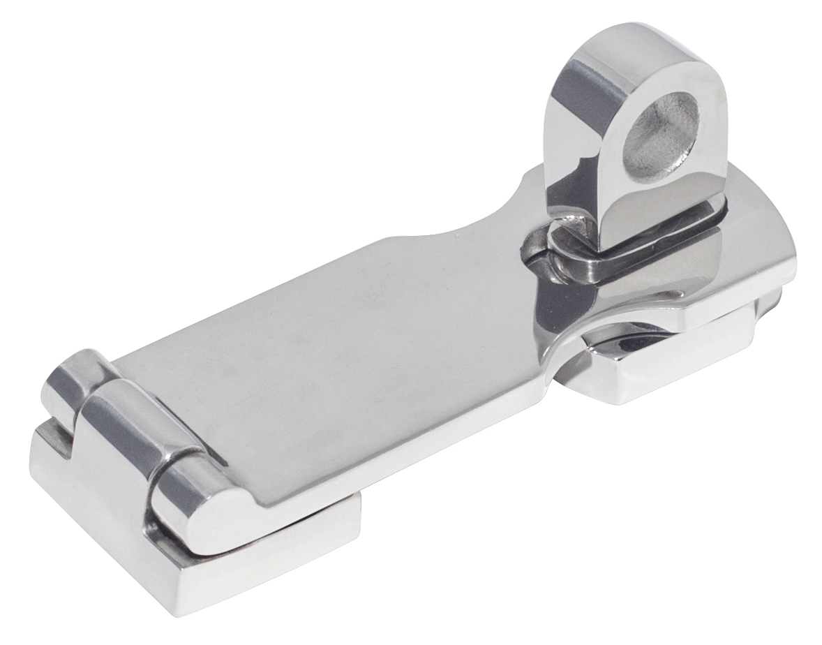
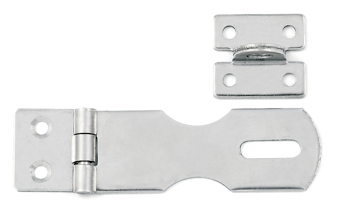
Hasps with hinged plate and catch. Configurations differ in material, length and geometry: match the table row to its drawing before selecting the fixing hardware.
- Material
- AISI 304 / A2; AISI 316 / A4
Technical drawing
Dimensions in mm. Illustrative drawings, not to scale. Dimensions may vary between batches: check the delivered product before drilling. A dash denotes a dimension not specified in the source, requiring confirmation.
Configuration 1
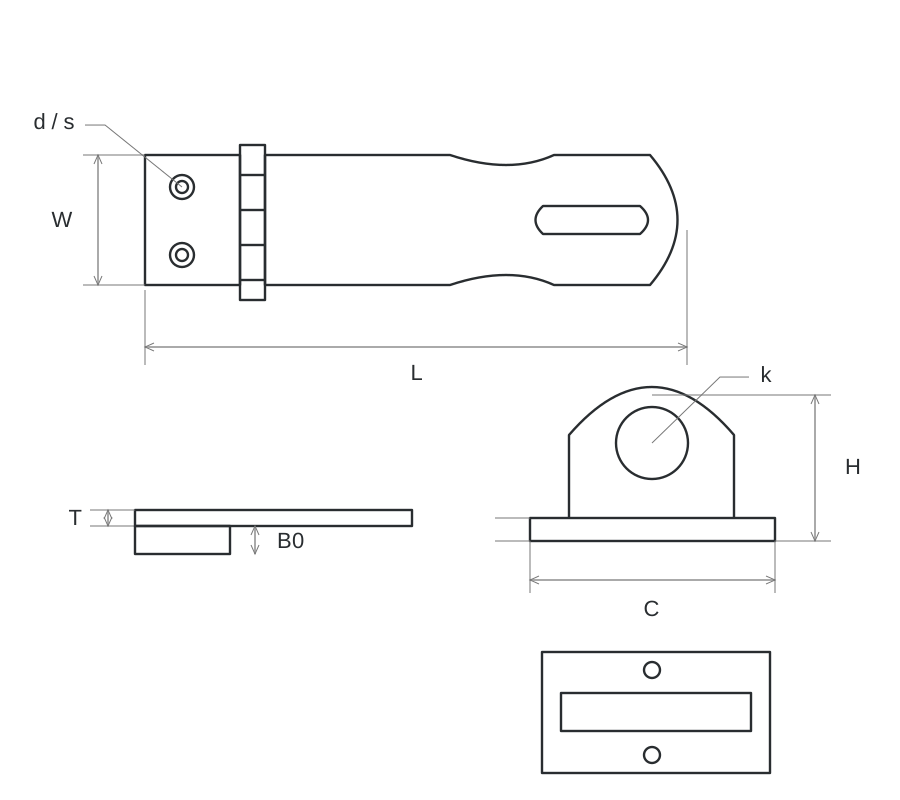
L: overall length; W: plate width; H: mounted eye height; d/s: plate hole and countersink diameters; T: plate thickness; T1: catch-base thickness; C/W2: catch-base length/width; k: padlock-hole diameter. L1: hinged-base length; L2: indicated straight plate segment; L3: hole-centre distance from hinge reference; L4: transverse base-hole spacing; L5/W1: slot length/width; L6: longitudinal catch-hole spacing. Type 1: the source does not specify hole centre distances. B0: hinged-base thickness, 5 mm.
Configuration 2
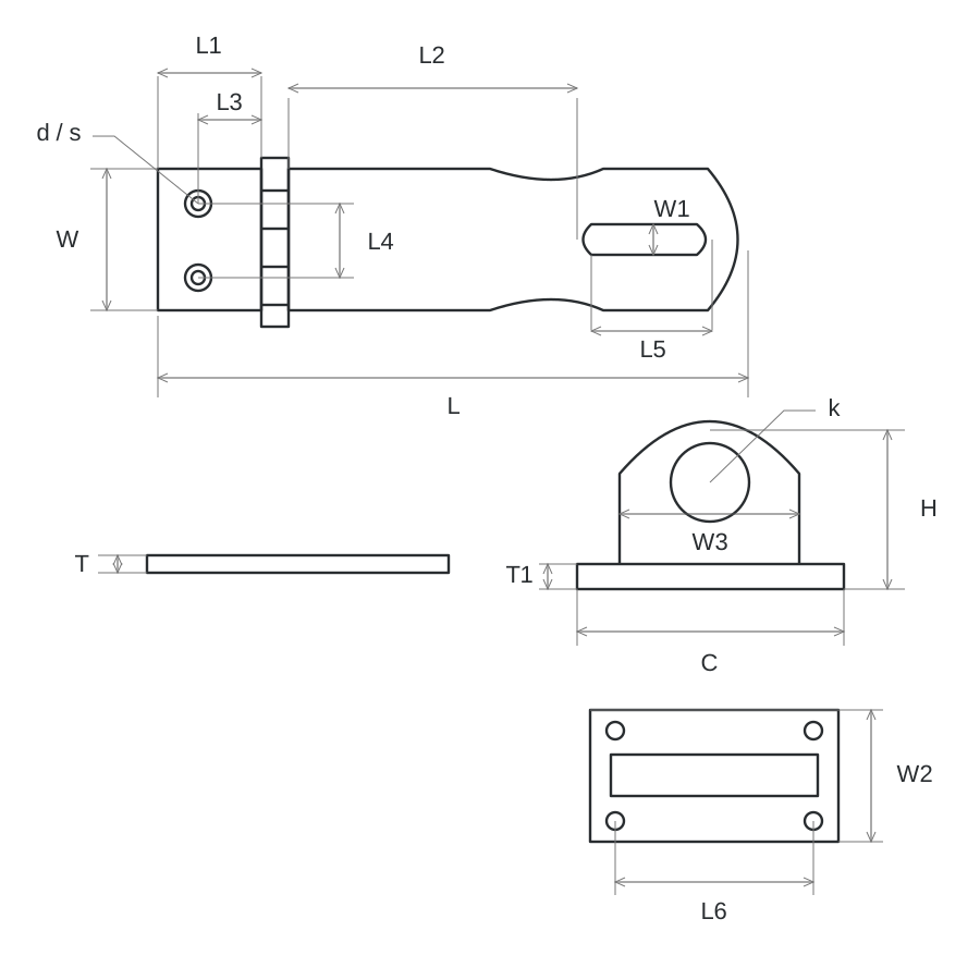
L: overall length; W: plate width; H: mounted eye height; d/s: plate hole and countersink diameters; T: plate thickness; T1: catch-base thickness; C/W2: catch-base length/width; k: padlock-hole diameter. L1: hinged-base length; L2: indicated straight plate segment; L3: hole-centre distance from hinge reference; L4: transverse base-hole spacing; L5/W1: slot length/width; L6: longitudinal catch-hole spacing. Type 2: catch holes also 4.5 mm, countersinks 8 mm. Tolerances: L and L1 ±5%; d/s/k +5%/−2%; L2–L6/H/W/W1/W2/C ±5%; T/T1 +0/−0.13 mm. W3: outside eye width, 15 mm (±5%).
Configuration A
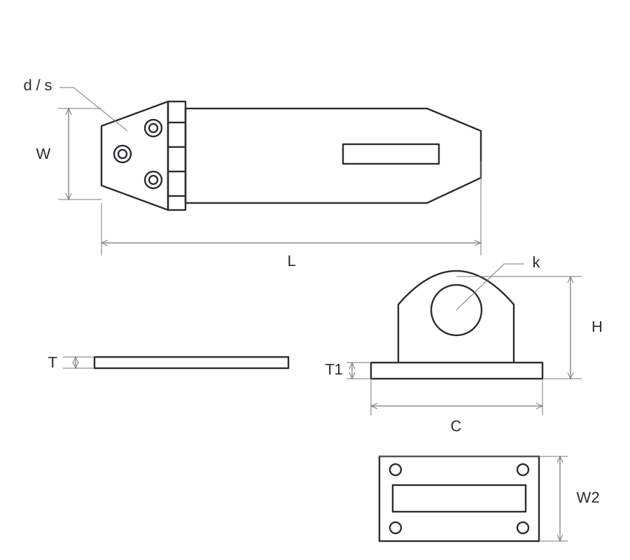
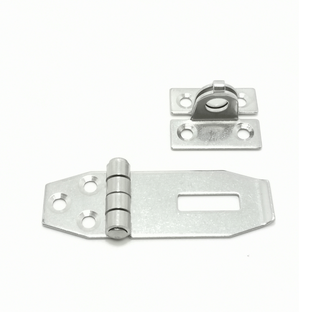
L: overall length; W: plate width; H: mounted eye height; d/s: plate hole and countersink diameters; T: plate thickness; T1: catch-base thickness; C/W2: catch-base length/width; k: padlock-hole diameter. L1: hinged-base length; L2: indicated straight plate segment; L3: hole-centre distance from hinge reference; L4: transverse base-hole spacing; L5/W1: slot length/width; L6: longitudinal catch-hole spacing. Type A: short 75 mm version. Tolerances: L ±3%; C ±5%; W/W2 ±1 mm; T +0/−0.13 mm; H +1/0 mm; d ±0.5 mm.
Configuration B
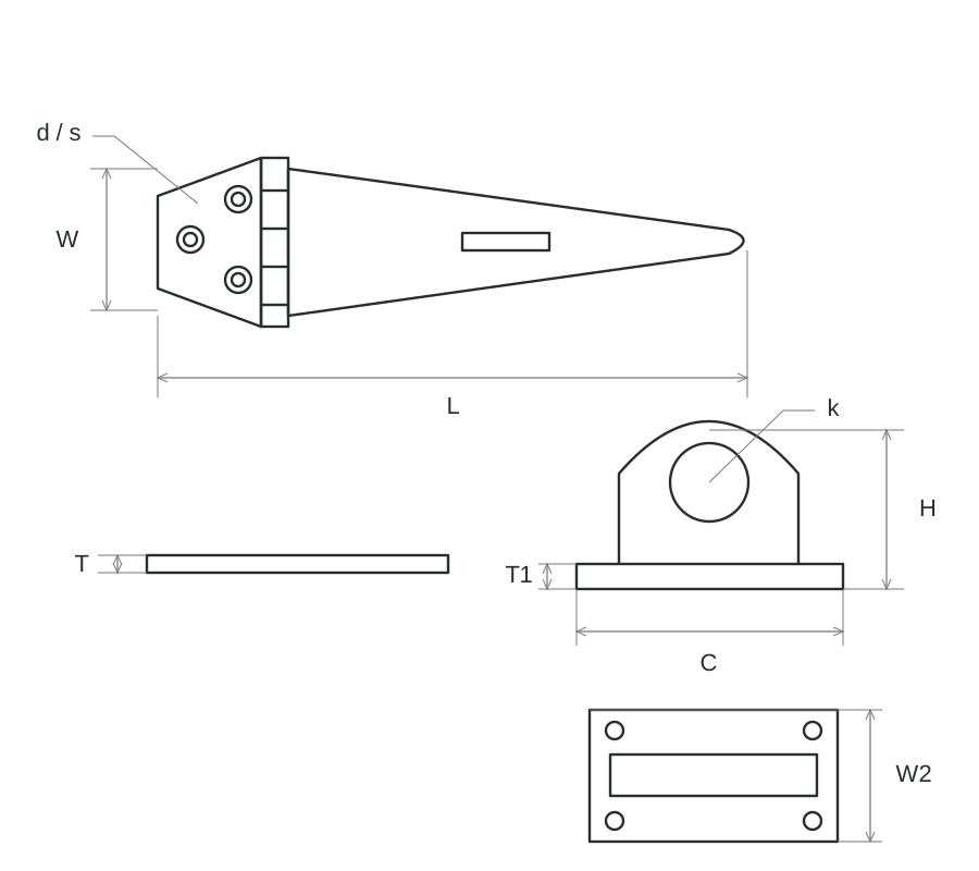
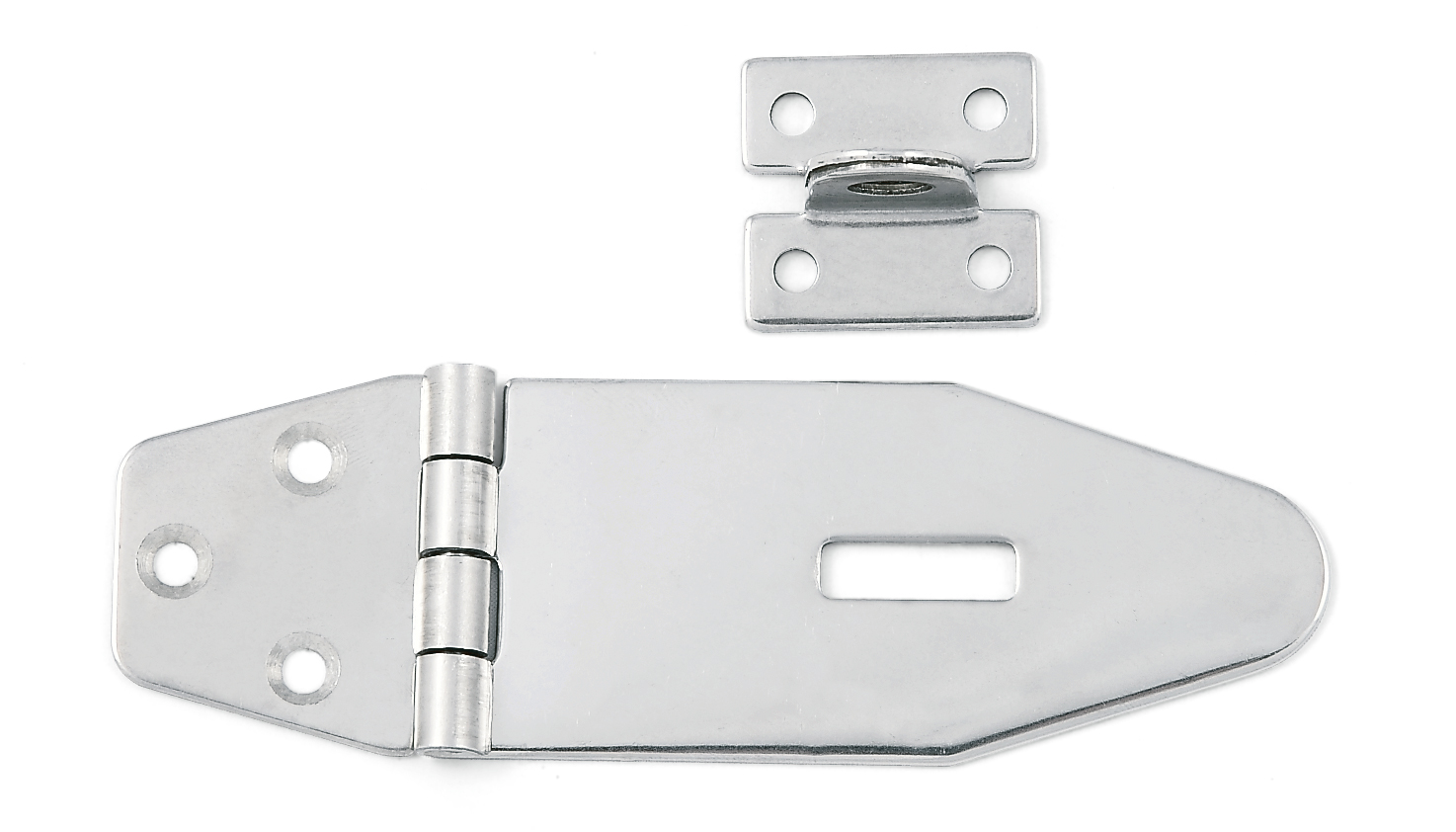
L: overall length; W: plate width; H: mounted eye height; d/s: plate hole and countersink diameters; T: plate thickness; T1: catch-base thickness; C/W2: catch-base length/width; k: padlock-hole diameter. L1: hinged-base length; L2: indicated straight plate segment; L3: hole-centre distance from hinge reference; L4: transverse base-hole spacing; L5/W1: slot length/width; L6: longitudinal catch-hole spacing. Type B: 125 mm configuration, labelled type A in the older catalogue. Catch holes 4.5 mm. Tolerances: L/C/H/W/W2 ±5%; d/s/k +5%/−2%; T/T1 +0/−0.13 mm.
Variants and dimensional data
| Type | Material | L (mm) | W (mm) | H (mm) | d (mm) | s (mm) | T (mm) | T1 (mm) | C (mm) | W2 (mm) | k (mm) | L1 (mm) | L2 (mm) | L3 (mm) | L4 (mm) | L5 (mm) | L6 (mm) | W1 (mm) | W3 (mm) | B0 (mm) | RFQ |
|---|---|---|---|---|---|---|---|---|---|---|---|---|---|---|---|---|---|---|---|---|---|
| 1 | AISI 316 / A4 | 75 | 25,5 | 20 | 4,3 | 8 | 4 | — | 26,3 | — | 8 | — | — | — | — | — | — | — | — | 5 | |
| 2 | AISI 304 / A2 | 100 | 28 | 19 | 4,5 | 8 | 1,5 | 1,5 | 32 | 30 | 8 | 21 | 54 | 12 | 14 | 20 | 20 | 8 | 15 | — | |
| A | AISI 304 / A2 | 75 | 25 | 19 | 4,5 | 8 | 1,5 | — | 32 | 30 | — | — | — | — | — | — | — | — | — | — | |
| B | AISI 304 / A2 | 125 | 40 | 19 | 4,5 | 8 | 1,5 | 1,5 | 31 | 29 | 8,5 | — | — | — | — | — | — | — | — | — |
Letter symbols are harmonised with the Dueemme drawings. Configuration B corresponds to type A in the older catalogue; type A shown here is the short 75 mm version. No padlock security certification is provided.
Materials and finishes
- Material
- AISI 304 / A2; AISI 316 / A4
Material of the documented configuration. Specify supply conditions and finishes in the enquiry.
Documentation and supply
State the quantity, application and documentation requirements in your enquiry. Availability and configuration are confirmed for the individual requirement.
Request a quote
Hasps and staples