
Internally threaded and drop-in anchors
An internal thread receives a compatible bolt or rod. Drop-in designs may require a dedicated setting operation before the threaded element is inserted.
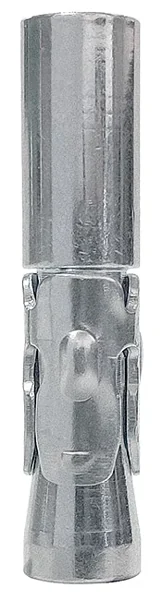
Features and selection criteria
The M thread size does not necessarily equal drill diameter. Check setting depth, thread engagement, bolt grade and expansion verification method.
Dimensions transcribed from the listed sources, checked on 13 November 2026. “—” means not stated or not normalised, not zero. Nominal diameter, thread and drill diameter are distinct. Consult the specific variant documentation for loads, installation and permitted applications. Availability is confirmed at quotation.
Designs, materials and substrates
This family contains 10 series or reference groups, with 52 catalogue rows. Series photographs help distinguish geometries and fixing methods; they do not necessarily represent every size in the range.
Documented materials
Steel · Stainless A4 · Brass
Substrates mentioned in the sources
Concrete · Cracked concrete
This list describes the family and does not assign every substrate to every variant.
Information to define before selection
| Parameter | What to check |
|---|---|
| Load-bearing substrate | Material type, strength, any cracking, useful thickness and hole conditions. Compatibility must be established for the selected design and size. |
| Fixing geometry | Total length, body or thread diameter and drill diameter are distinct parameters. Through-fixings must allow for fixture thickness and non-load-bearing layers. |
| Depth and distances | Compare hole depth, nominal or effective anchorage depth, edge distances and spacing. A deeper hole does not automatically increase fixing capacity. |
| Environment and exposure | Check material and coating of all components, temperature and service conditions. A2, A4 and HCR stainless designs require selection appropriate to the environment. |
| Loads and documentation | Define action directions and combinations and check the part-specific document. Dimensional data identify the part but do not replace a design verification. |
Installation sequence to verify
- Distinguish internal thread, body diameter and substrate hole.
- Check depth and anchor-mouth position.
- For designs requiring it, activate expansion before fitting the bolt.
- Maintain engagement length and the grade of the matching threaded element.
This sequence guides the reading of the instructions. Diameters, depths, equipment and tightening values remain those of the specific variant.
Series and technical tables
ABT01Tecfi · 4 referencesAnchor body with an internal thread for a compatible bolt or rod. Thread diameter must be distinguished from outside diameter and installation hole.Full description and technical table ↓
Series characteristics ABT01
Anchor body with an internal thread for a compatible bolt or rod. Thread diameter must be distinguished from outside diameter and installation hole.
Materials represented by the variants: Steel.
Documented series dimensions: nominal Ø 8–16 mm; length 45–75 mm. Endpoints describe the listed sizes rather than a continuous range. Use the part-specific row for each combination.
The M thread size does not necessarily equal drill diameter. Check setting depth, thread engagement, bolt grade and expansion verification method.
The table lists available characteristics for each reference; alternative installation configurations remain separate. Refer to the linked documents for torque, loads and conditions not specified in the table.
View the manufacturer’s product page ↗Part-specific technical table
Values and symbols follow the source. “—” = not stated in the table, not zero. The std, red1 and red2 designations identify different manufacturer configurations.
| Part number and source | Nominal Ø dnom (mm) | Length L (mm) | Material | Finish | Misura M |
|---|---|---|---|---|---|
| Tecfi ABT 01 08 045 | 8 | 45 | Steel | Zinc plated | M6 |
| Tecfi ABT 01 10 050 | 10 | 50 | Steel | Zinc plated | M8 |
| Tecfi ABT 01 12 060 | 12 | 60 | Steel | Zinc plated | M10 |
| Tecfi ABT 01 16 075 | 16 | 75 | Steel | Zinc plated | M12 |
System documents
ETA, fire or seismic indicators listed for one part do not extend to other sizes. Permissible loads and torque values not listed here must be obtained from the applicable document and actual configuration.
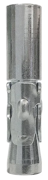 ABT71Tecfi · 4 referencesAnchor body with an internal thread for a compatible bolt or rod. Thread diameter must be distinguished from outside diameter and installation hole.Full description and technical table ↓
Series characteristics ABT71
Anchor body with an internal thread for a compatible bolt or rod. Thread diameter must be distinguished from outside diameter and installation hole.
Materials represented by the variants: Stainless A4.
Documented series dimensions: nominal Ø 8–16 mm; length 45–75 mm. Endpoints describe the listed sizes rather than a continuous range. Use the part-specific row for each combination.
The M thread size does not necessarily equal drill diameter. Check setting depth, thread engagement, bolt grade and expansion verification method.
The table lists available characteristics for each reference; alternative installation configurations remain separate. Refer to the linked documents for torque, loads and conditions not specified in the table.
View the manufacturer’s product page ↗Part-specific technical table
Values and symbols follow the source. “—” = not stated in the table, not zero. The std, red1 and red2 designations identify different manufacturer configurations.
| Part number and source | Nominal Ø dnom (mm) | Length L (mm) | Material | Misura M |
|---|---|---|---|---|
| Tecfi ABT 71 08 045 | 8 | 45 | Acciaio Inox A4 | M6 |
| Tecfi ABT 71 10 050 | 10 | 50 | Acciaio Inox A4 | M8 |
| Tecfi ABT 71 12 060 | 12 | 60 | Acciaio Inox A4 | M10 |
| Tecfi ABT 71 16 075 | 16 | 75 | Acciaio Inox A4 | M12 |
System documents
ETA, fire or seismic indicators listed for one part do not extend to other sizes. Permissible loads and torque values not listed here must be obtained from the applicable document and actual configuration.
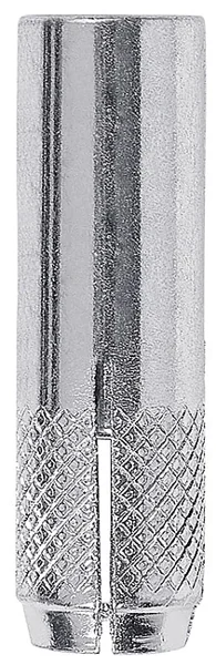 HL01Tecfi · 6 referencesAnchor body with an internal thread for a compatible bolt or rod. Thread diameter must be distinguished from outside diameter and installation hole.Full description and technical table ↓
Series characteristics HL01
Anchor body with an internal thread for a compatible bolt or rod. Thread diameter must be distinguished from outside diameter and installation hole.
Materials represented by the variants: Steel.
Documented series dimensions: nominal Ø 8–25 mm; length 25–80 mm. Endpoints describe the listed sizes rather than a continuous range. Use the part-specific row for each combination.
The M thread size does not necessarily equal drill diameter. Check setting depth, thread engagement, bolt grade and expansion verification method.
The table lists available characteristics for each reference; alternative installation configurations remain separate. Refer to the linked documents for torque, loads and conditions not specified in the table.
View the manufacturer’s product page ↗Part-specific technical table
Values and symbols follow the source. “—” = not stated in the table, not zero. The std, red1 and red2 designations identify different manufacturer configurations.
| Part number and source | Nominal Ø dnom (mm) | Length L (mm) | Material | Finish |
|---|---|---|---|---|
| Tecfi HL 01 06 025 | 8 | 25 | Steel | Zinc plated |
| Tecfi HL 01 08 030 | 10 | 30 | Steel | Zinc plated |
| Tecfi HL 01 10 040 | 12 | 40 | Steel | Zinc plated |
| Tecfi HL 01 12 050 | 15 | 50 | Steel | Zinc plated |
| Tecfi HL 01 16 065 | 20 | 65 | Steel | Zinc plated |
| Tecfi HL 01 20 080 | 25 | 80 | Steel | Zinc plated |
System documents
ETA, fire or seismic indicators listed for one part do not extend to other sizes. Permissible loads and torque values not listed here must be obtained from the applicable document and actual configuration.
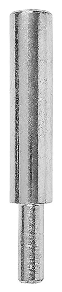 HM01Tecfi · 6 referencesAnchor body with an internal thread for a compatible bolt or rod. Thread diameter must be distinguished from outside diameter and installation hole.Full description and technical table ↓
Series characteristics HM01
Anchor body with an internal thread for a compatible bolt or rod. Thread diameter must be distinguished from outside diameter and installation hole.
Materials represented by the variants: Steel.
The M thread size does not necessarily equal drill diameter. Check setting depth, thread engagement, bolt grade and expansion verification method.
The table lists available characteristics for each reference; alternative installation configurations remain separate. Refer to the linked documents for torque, loads and conditions not specified in the table.
View the manufacturer’s product page ↗Part-specific technical table
Values and symbols follow the source. “—” = not stated in the table, not zero. The std, red1 and red2 designations identify different manufacturer configurations.
| Part number and source | Material | Finish | Per ancorante M |
|---|---|---|---|
| Tecfi HM 01 06 115 | Steel | Zinc plated | M6 |
| Tecfi HM 01 08 115 | Steel | Zinc plated | M8 |
| Tecfi HM 01 10 127 | Steel | Zinc plated | M10 |
| Tecfi HM 01 12 140 | Steel | Zinc plated | M12 |
| Tecfi HM 01 16 152 | Steel | Zinc plated | M16 |
| Tecfi HM 01 20 152 | Steel | Zinc plated | M20 |
ETA, fire or seismic indicators listed for one part do not extend to other sizes. Permissible loads and torque values not listed here must be obtained from the applicable document and actual configuration.
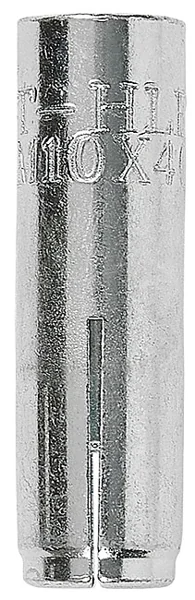 HLE01Tecfi · 6 referencesAnchor body with an internal thread for a compatible bolt or rod. Thread diameter must be distinguished from outside diameter and installation hole.Full description and technical table ↓
Series characteristics HLE01
Anchor body with an internal thread for a compatible bolt or rod. Thread diameter must be distinguished from outside diameter and installation hole.
Materials represented by the variants: Steel.
Documented series dimensions: nominal Ø 8–20 mm. Endpoints describe the listed sizes rather than a continuous range. Use the part-specific row for each combination.
Substrates mentioned in the series sources: Concrete, Cracked concrete. Check the application scope for the individual part.
The M thread size does not necessarily equal drill diameter. Check setting depth, thread engagement, bolt grade and expansion verification method.
The table lists available characteristics for each reference; alternative installation configurations remain separate. Refer to the linked documents for torque, loads and conditions not specified in the table.
View the manufacturer’s product page ↗Part-specific technical table
Values and symbols follow the source. “—” = not stated in the table, not zero. The std, red1 and red2 designations identify different manufacturer configurations.
| Part number and source | Nominal Ø dnom (mm) | Material | Finish | Part-specific documentation indicators |
|---|---|---|---|---|
| Tecfi HLE 01 06 025 | 8 | Steel | Zinc plated | ETA-CE · EAD 330232-00-0601 ETA-CE · EAD 330747-00-0601 R120 (TR 020) |
| Tecfi HLE 01 08 030 | 10 | Steel | Zinc plated | ETA-CE · EAD 330232-00-0601 ETA-CE · EAD 330747-00-0601 R120 (TR 020) |
| Tecfi HLE 01 10 030 | 12 | Steel | Zinc plated | ETA-CE · EAD 330232-00-0601 ETA-CE · EAD 330747-00-0601 R120 (TR 020) |
| Tecfi HLE 01 10 040 | 12 | Steel | Zinc plated | ETA-CE · EAD 330232-00-0601 ETA-CE · EAD 330747-00-0601 R120 (TR 020) |
| Tecfi HLE 01 12 050 | 15 | Steel | Zinc plated | ETA-CE · EAD 330232-00-0601 ETA-CE · EAD 330747-00-0601 R120 (TR 020) |
| Tecfi HLE 01 16 065 | 20 | Steel | Zinc plated | ETA-CE · EAD 330232-00-0601 ETA-CE · EAD 330747-00-0601 R120 (TR 020) |
System documents
ETA, fire or seismic indicators listed for one part do not extend to other sizes. Permissible loads and torque values not listed here must be obtained from the applicable document and actual configuration.
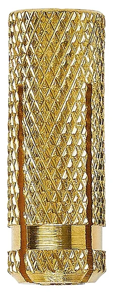 AK01Tecfi · 7 referencesAnchor body with an internal thread for a compatible bolt or rod. Thread diameter must be distinguished from outside diameter and installation hole.Full description and technical table ↓
Series characteristics AK01
Anchor body with an internal thread for a compatible bolt or rod. Thread diameter must be distinguished from outside diameter and installation hole.
Materials represented by the variants: Brass.
Documented series dimensions: nominal Ø 5–18 mm; length 16–42 mm. Endpoints describe the listed sizes rather than a continuous range. Use the part-specific row for each combination.
The M thread size does not necessarily equal drill diameter. Check setting depth, thread engagement, bolt grade and expansion verification method.
The table lists available characteristics for each reference; alternative installation configurations remain separate. Refer to the linked documents for torque, loads and conditions not specified in the table.
View the manufacturer’s product page ↗Part-specific technical table
Values and symbols follow the source. “—” = not stated in the table, not zero. The std, red1 and red2 designations identify different manufacturer configurations.
| Part number and source | Nominal Ø dnom (mm) | Length L (mm) | Material | Finish | Misura M |
|---|---|---|---|---|---|
| Tecfi AK 01 00 004 | 5 | 16 | Brass | Brass | M4 |
| Tecfi AK 01 00 005 | 6.5 | 20.5 | Brass | Brass | M5 |
| Tecfi AK 01 00 006 | 8 | 23.5 | Brass | Brass | M6 |
| Tecfi AK 01 00 008 | 10 | 28 | Brass | Brass | M8 |
| Tecfi AK 01 00 010 | 12 | 33 | Brass | Brass | M10 |
| Tecfi AK 01 00 012 | 15 | 38 | Brass | Brass | M12 |
| Tecfi AK 01 00 014 | 18 | 42 | Brass | Brass | M14 |
System documents
ETA, fire or seismic indicators listed for one part do not extend to other sizes. Permissible loads and torque values not listed here must be obtained from the applicable document and actual configuration.
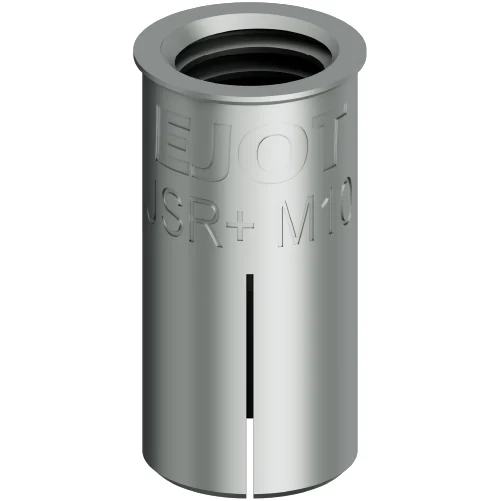 Drop-in JSR+EJOT · 2 referencesAnchor body with an internal thread for a compatible bolt or rod. Thread diameter must be distinguished from outside diameter and installation hole.Full description and technical table ↓
Series characteristics Drop-in JSR+
Anchor body with an internal thread for a compatible bolt or rod. Thread diameter must be distinguished from outside diameter and installation hole.
Materials represented by the variants: Steel.
Documented series dimensions: length 25 mm. Endpoints describe the listed sizes rather than a continuous range. Use the part-specific row for each combination.
Substrates mentioned in the series sources: Concrete, Cracked concrete. Check the application scope for the individual part.
The M thread size does not necessarily equal drill diameter. Check setting depth, thread engagement, bolt grade and expansion verification method.
The table lists available characteristics for each reference; alternative installation configurations remain separate. Refer to the linked documents for torque, loads and conditions not specified in the table.
View the manufacturer’s product page ↗Part-specific technical table
Values and symbols follow the source. “—” = not stated in the table, not zero. The std, red1 and red2 designations identify different manufacturer configurations.
| Part number and source | Material | Thread | Length (mm) | Drill Ø (mm) |
|---|---|---|---|---|
| EJOT 9650070108 | Acciaio zincato, galvanizzato | M8 | 25.0 | 10.0 |
| EJOT 9650070110 | Acciaio zincato, galvanizzato | M10 | 25.0 | 12.0 |
System documents
ETA, fire or seismic indicators listed for one part do not extend to other sizes. Permissible loads and torque values not listed here must be obtained from the applicable document and actual configuration.
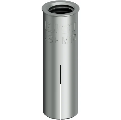 Drop-in JS+EJOT · 5 referencesAnchor body with an internal thread for a compatible bolt or rod. Thread diameter must be distinguished from outside diameter and installation hole.Full description and technical table ↓
Series characteristics Drop-in JS+
Anchor body with an internal thread for a compatible bolt or rod. Thread diameter must be distinguished from outside diameter and installation hole.
Materials represented by the variants: Steel.
Substrates mentioned in the series sources: Concrete, Cracked concrete. Check the application scope for the individual part.
The M thread size does not necessarily equal drill diameter. Check setting depth, thread engagement, bolt grade and expansion verification method.
The table lists available characteristics for each reference; alternative installation configurations remain separate. Refer to the linked documents for torque, loads and conditions not specified in the table.
View the manufacturer’s product page ↗Part-specific technical table
Values and symbols follow the source. “—” = not stated in the table, not zero. The std, red1 and red2 designations identify different manufacturer configurations.
| Part number and source | Material | Thread |
|---|---|---|
| EJOT 9650070106 | Acciaio zincato, galvanizzato | M6 |
| EJOT 9650070107 | Acciaio zincato, galvanizzato | M8 |
| EJOT 9650070109 | Acciaio zincato, galvanizzato | M10 |
| EJOT 9650070111 | Acciaio zincato, galvanizzato | M12 |
| EJOT 9650070112 | Acciaio zincato, galvanizzato | M16 |
System documents
ETA, fire or seismic indicators listed for one part do not extend to other sizes. Permissible loads and torque values not listed here must be obtained from the applicable document and actual configuration.
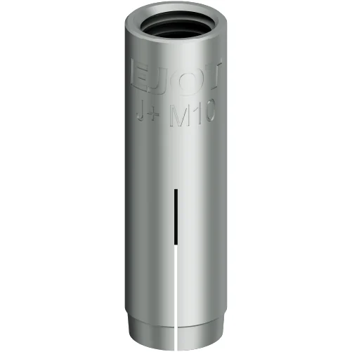 Drop-in J+EJOT · 6 referencesAnchor body with an internal thread for a compatible bolt or rod. Thread diameter must be distinguished from outside diameter and installation hole.Full description and technical table ↓
Series characteristics Drop-in J+
Anchor body with an internal thread for a compatible bolt or rod. Thread diameter must be distinguished from outside diameter and installation hole.
Materials represented by the variants: Steel.
Documented series dimensions: length 25–80 mm. Endpoints describe the listed sizes rather than a continuous range. Use the part-specific row for each combination.
Substrates mentioned in the series sources: Concrete, Cracked concrete. Check the application scope for the individual part.
The M thread size does not necessarily equal drill diameter. Check setting depth, thread engagement, bolt grade and expansion verification method.
The table lists available characteristics for each reference; alternative installation configurations remain separate. Refer to the linked documents for torque, loads and conditions not specified in the table.
View the manufacturer’s product page ↗Part-specific technical table
Values and symbols follow the source. “—” = not stated in the table, not zero. The std, red1 and red2 designations identify different manufacturer configurations.
| Part number and source | Material | Thread | Length (mm) | Drill Ø (mm) |
|---|---|---|---|---|
| EJOT 9650070100 | Acciaio zincato, galvanizzato | M6 | 25.0 | 8.0 |
| EJOT 9650070101 | Acciaio zincato, galvanizzato | M8 | 30.0 | 10.0 |
| EJOT 9650070102 | Acciaio zincato, galvanizzato | M10 | 40.0 | 10.0 |
| EJOT 9650070103 | Acciaio zincato, galvanizzato | M12 | 50.0 | 15.0 |
| EJOT 9650070104 | Acciaio zincato, galvanizzato | M16 | 65.0 | 20.0 |
| EJOT 9650070105 | Acciaio zincato, galvanizzato | M20 | 80.0 | 25.0 |
System documents
ETA, fire or seismic indicators listed for one part do not extend to other sizes. Permissible loads and torque values not listed here must be obtained from the applicable document and actual configuration.
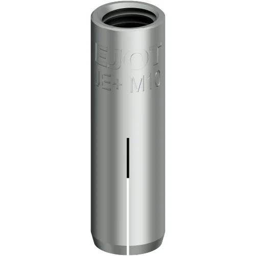 Drop-in JE+EJOT · 6 referencesAnchor body with an internal thread for a compatible bolt or rod. Thread diameter must be distinguished from outside diameter and installation hole.Full description and technical table ↓
Series characteristics Drop-in JE+
Anchor body with an internal thread for a compatible bolt or rod. Thread diameter must be distinguished from outside diameter and installation hole.
Materials represented by the variants: Stainless A4.
Documented series dimensions: length 25–80 mm. Endpoints describe the listed sizes rather than a continuous range. Use the part-specific row for each combination.
Substrates mentioned in the series sources: Concrete, Cracked concrete. Check the application scope for the individual part.
The M thread size does not necessarily equal drill diameter. Check setting depth, thread engagement, bolt grade and expansion verification method.
The table lists available characteristics for each reference; alternative installation configurations remain separate. Refer to the linked documents for torque, loads and conditions not specified in the table.
View the manufacturer’s product page ↗Part-specific technical table
Values and symbols follow the source. “—” = not stated in the table, not zero. The std, red1 and red2 designations identify different manufacturer configurations.
| Part number and source | Material | Length (mm) | Drill Ø (mm) |
|---|---|---|---|
| EJOT 9650070113 | Acciaio inox (A4) | 25.0 | 8.0 |
| EJOT 9650070114 | Acciaio inox (A4) | 30.0 | 10.0 |
| EJOT 9650070115 | Acciaio inox (A4) | 40.0 | 12.0 |
| EJOT 9650070116 | Acciaio inox (A4) | 50.0 | 15.0 |
| EJOT 9650070117 | Acciaio inox (A4) | 65.0 | 20.0 |
| EJOT 9650070118 | Acciaio inox (A4) | 80.0 | 25.0 |
System documents
ETA, fire or seismic indicators listed for one part do not extend to other sizes. Permissible loads and torque values not listed here must be obtained from the applicable document and actual configuration.
Anchor finder
Search by part number or select declared characteristics. Missing data do not satisfy a dimensional filter.
Request technical review or a quotation
Select a finder reference or describe the application.
FAQ
How do I select an anchor?
Start with substrate, load and environment, then identify configuration, depth, distances and part-specific documentation. The finder selects catalogue references and does not perform a design check.
Does equal diameter mean equal capacity?
No. Geometry, material, anchorage and technical assessment may differ. Dimensional comparison does not establish technical equivalence or interchangeability.
Do all anchors have an ETA and CE marking?
These cannot be assigned to an entire category. Check the product documentation, scope and applicability to the specific size. An ETA link does not extend its assessment to other parts.
What information is needed for an enquiry?
Part number or family, quantity, substrate material and condition, thicknesses, fixing geometry, environment, actions and required documents. For resins, also specify temperature and hole conditions.
Sources and documentation
Dimensions transcribed from the listed sources, checked on 13 November 2026. “—” means not stated or not normalised, not zero. Nominal diameter, thread and drill diameter are distinct. Consult the specific variant documentation for loads, installation and permitted applications. Availability is confirmed at quotation.
Dueemme Sidol S.r.l. · Sesto San Giovanni, Milan · Supply for industrial customers and OEMs.